CS92 Energy Code Feasibility Study in Brockton, Massachusetts
Energy code feasibility study for a 41-unit high-rise in Massachusetts. Compares multiple design paths. Recommended: PROPOSED (All-Electric). View full study.
- Study Type
- Energy Code Feasibility Study
- State
- Massachusetts
- Units
- 41
- Building Type
- high-rise
- Fuel Type
- All-Electric
- Recommended Path
- PROPOSED (All-Electric)
Goal
To find the most cost-effective compliance path, this report isolates energy code related costs from total construction. We use real bid data from vendors & clients to create a reliable framework for aligning incentives and design, with all recommendations confirmed by detailed energy modeling.
Project
- Brockton, MA 02301
- 1 Building | 41 Units | 37,782 SF Conditioned
- New Construction | 6-story high-rise multifamily (x1)
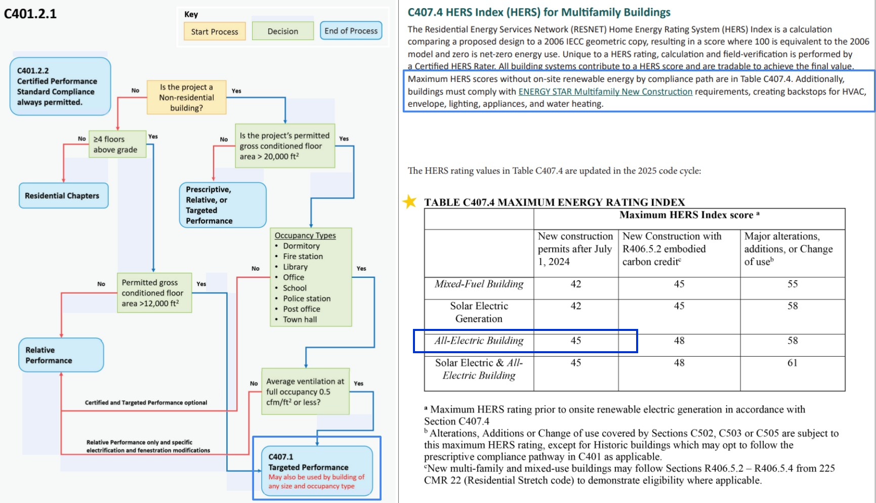
- All-Electric | 2021 IECC with MA Amendments (Stretch Code) | HERS ≤ 45 | ENERGY STAR MFNC v1.2
Overview
Read This: This report compares different ways you can build the project and meet energy code, looking at both cost and incentives, with the ultimate goal as finding the most affordable path.
- The overview outlines the key differences between each of the paths we show in this report and why we recommend the one we picked over the others.
- The recommended design section is where we share the requirements and incentives for the path we think is best based on affordability.
- The path comparison section shows the detailed requirements and incentives for each path we compared, basically showing our work if you want to dig in.
Product Recs: All product recommendations are recommendations only and can be substituted with any equivalent or better match.
Path Summaries
Both paths are all-electric new construction under the Massachusetts Stretch Code HERS 45 ceiling, both certify for ENERGY STAR Multifamily New Construction, and PROPOSED costs less before the incentive and after it.
PROPOSED (All-Electric): Recommended
The goal of this path was to show an all-electric new-construction design under the Massachusetts Stretch Code HERS 45 ceiling that certifies for ENERGY STAR Multifamily New Construction, because it meets that ceiling at a lower cost. The estimated energy-related cost is $59.32/sf with a $1.90/sf incentive, for a net of $58.46/sf. The main advantage of this path is the lower construction cost, before the incentive and after it, and a simpler floor line, because floors 1 and 2 are steel and floors 3 through 5 are wood, and those floors use the same continuous insulation, so the floor bands do not need an insulation transition. It meets the Massachusetts Stretch Code and certifies for ENERGY STAR Multifamily New Construction, with the air barrier on the sheathing and the roof air barrier on the deck, and it keeps off costly upgrades like the extra attic insulation and the lower-U windows.
HPWH (All-Electric): Alternative
The goal of this path was to show an all-electric new-construction package under the same Massachusetts Stretch Code HERS 45 ceiling and the same ENERGY STAR Multifamily New Construction certification, with more attic insulation and lower-U windows than PROPOSED. The estimated energy-related cost is $61.37/sf with a $1.90/sf incentive, for a net of $60.64/sf. The main advantage of this path is there is none, since the net is $2.18/sf more than PROPOSED, the incentive is the same, and the steel floors and the wood floors do not share one continuous insulation, so the floor bands need an insulation transition. It meets the Massachusetts Stretch Code and certifies for ENERGY STAR Multifamily New Construction, and the extra cost pays for the lower-U windows and an added attic insulation layer.
What Changes Between Paths
Item | HPWH | PROPOSED (Recommended) |
|---|---|---|
Exterior Walls | Floors 1-2: ≥ R-21 cavity insulation (2x6 steel @ 16" o.c.) with ≥ R-5 continuous exterior insulation. Floors 3-5: ≥ R-23 cavity insulation (2x6 wood @ 16" o.c.), no continuous insulation. Suitable alternative for the steel wall: ≥ R-13 cavity plus ≥ R-10 continuous. | Floors 1-2: ≥ R-21 cavity insulation (2x6 steel @ 16" o.c., 5.5 in) with ≥ R-3.8 polyiso continuous exterior insulation (1 in). Floors 3-5: ≥ R-21 cavity insulation (2x6 wood @ 16" o.c., 5.5 in) with ≥ R-3.8 polyiso continuous exterior insulation (1 in). Steel and wood share the same R-3.8 continuous insulation, so there is no insulation transition between floors. Suitable alternative for the steel wall: ≥ R-13 cavity plus ≥ R-10 continuous. |
Roof | Sealed attic: ≥ R-19 insulation + ≥ R-30 continuous insulation. | Sealed attic: ≥ R-30 continuous insulation. |
Windows & Glass Doors | High performance, U ≤ 0.25 / SHGC ≤ 0.25. | High performance, U ≤ 0.27 / SHGC ≤ 0.30. |
Cost $/sf | $61.37 | $59.32 |
Incentive $/sf | $1.90 | $1.90 |
Net $/sf | $60.64 | $58.46 |
Permit / Certificate of Occupancy Requirements
Multifamily Buildings
Code Path
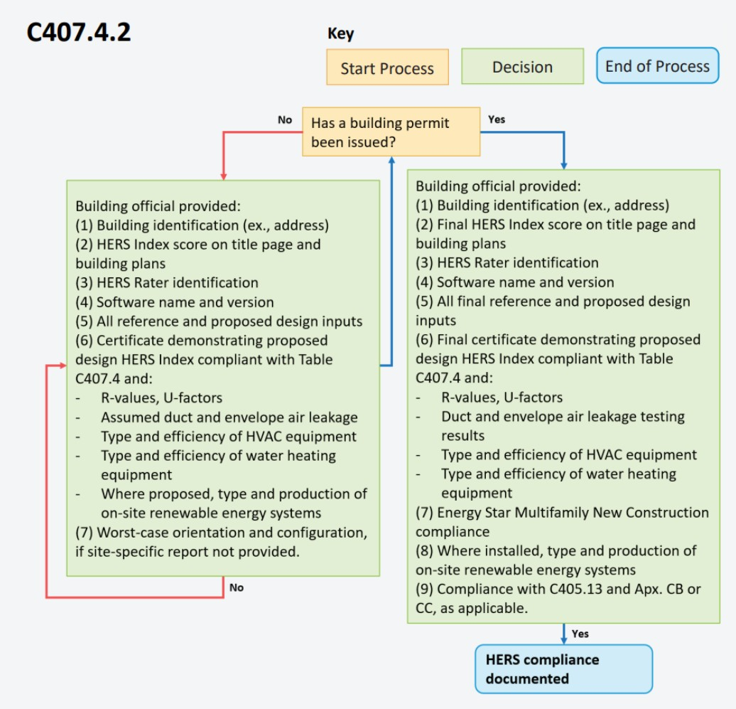
- HERS: Brockton is a Stretch Code town. The buildings are 6-story Group R under 225 CMR 23, and the dwelling units comply by per-unit HERS under section C407.4. The all-electric Stretch ceiling is HERS ≤ 45 (Table C407.4, new construction column). Section C407.4.1 requires the building to meet ENERGY STAR Multifamily New Construction.
Permit Requirements
- HERS: With the building permit application, per 225 CMR 23 section C407.4.2.1: the proposed HERS Index on the title page and plans, the rater's name, the software name and version, all modeled inputs, and a certificate showing each dwelling unit type at or below the Table C407.4 ceiling, with the component specifications behind it (insulation R-values and U-factors, assumed duct and envelope leakage, and heating, cooling, ventilation, and water-heating types and efficiencies), on the worst-case orientation where no site-specific report is produced. ENERGY STAR Multifamily New Construction design review by the rater is part of that package (C407.4.1).
Certificate of Occupancy Requirements
- HERS: Before certificate of occupancy, per 225 CMR 23 section C407.4.2.2: the final HERS Index on the title page and plans, a confirmed as-built HERS certificate for each rated unit with the duct and envelope air-leakage test results and the installed equipment efficiencies, and documentation that each unit meets ENERGY STAR Multifamily New Construction (item 7). C405.13 EV-ready and Appendix CB solar-ready compliance close out with it (item 9). A certified HERS rater verifies the package (C407.4.3). Air-leakage testing follows ANSI/RESNET/ICC 380, and RESNET sampling is permitted because each building has more than 8 units (C402.5.2.2).
Recommended Design
This section outlines the design requirements, product recommendations, and incentives for the design that we believe will be the most affordable path to meeting energy code.
Recommended Design - Incentives
Incentives Available: $71,750 - $133,250
- MassSave Multifamily Program Energy Star Tier ($71,750) (Program Breakdown): You get this rebate for having your building(s) certified for the Energy Star MFNC v1.2 program. This requires pre-approval via an application to be submitted before construction starts. This rebate comes in the form of a check within 4 months of certification documentation being provided to MassSave, typically this is 4 months after construction is complete.
- DOER Alternative Energy Credits ($0 - $61,500) (Program Breakdown): This rebate is received for installing APS eligible air source heat pumps (click here for the list). There is an extensive process to get this incentive. It comes in the form of a check approximately 6-12 months after the heat pumps are installed and fully operational.
- IMPORTANT: Although an estimate is provided, this incentive can vary widely typically between $300-1,500 per heat pump. It's based on expected kWh usage of the system as well as the market value of the alternative energy credits when sold.
- Risks: Massachusetts is rewriting this program right now. The House bill would stop the state from accepting new applications on January 1, 2028, the Senate version leaves heat pumps out of that cutoff, and the two are in conference. The application needs the equipment installed and operating, so a project that will not reach that point before the deadline should treat this as upside rather than a budgeted line.
HVAC Design Loads
Plymouth County, MA · heating 9.0°F/70.0°F · cooling 88.0°F/75.0°F · all values kBtuh
Design heat loss · components
Unit type | Walls & rim joists | Roof / ceiling | Slab, floors & below grade | Windows & doors | Infiltration | Ventilation | Design heat loss | Design heat loss at selection |
|---|---|---|---|---|---|---|---|---|
1-Bedroom | 1.2 | 1.3 | 0.0 | 2.1 | 3.3 | 1.8 | 9.8 @ 9°F | 10.4 @ 5°F |
2-Bedroom | 3.0 | 1.1 | 0.0 | 3.5 | 4.9 | 2.4 | 14.9 @ 9°F | 15.9 @ 5°F |
3-Bedroom | 4.3 | 1.3 | 0.0 | 4.2 | 5.6 | 2.4 | 17.9 @ 9°F | 19.1 @ 5°F |
Design heat gain · components
Unit type | Solar through glazing | Envelope conduction | Internal gains | Infiltration & ventilation | Latent | Total heat gain | Sensible heat ratio |
|---|---|---|---|---|---|---|---|
1-Bedroom | 2.9 | 1.1 | 2.1 | 1.7 | 2.8 | 10.6 | 0.73 |
2-Bedroom | 4.0 | 1.7 | 2.3 | 2.3 | 3.9 | 14.2 | 0.72 |
3-Bedroom | 3.6 | 2.2 | 2.5 | 2.5 | 4.4 | 15.1 | 0.71 |
Selection
Unit type | Cooling Capacity | Minimum Heating Capacity |
|---|---|---|
1-Bedroom | 9.5 to 20.0 kBtuh rated | ≥ 10.4 kBtuh @ 5°F |
2-Bedroom | 12.8 to 20.0 kBtuh rated | ≥ 15.9 kBtuh @ 5°F |
3-Bedroom | 13.6 to 19.6 kBtuh rated | ≥ 19.1 kBtuh @ 5°F |
ENERGY STAR Total UA
Item | Detail |
|---|---|
Climate zone | IECC 5A (2021 IECC map) |
Program | ENERGY STAR MFNC National v1.2 Rev. 05 |
Rule | Design Review Item 2.1 / Fn 11-12; Proposed UA ≤ Reference UA |
Code reference | Exhibit 1 Table 1 (2021 IECC CZ); Design Review Item 2.1 / Fn 11-12 |
Version basis | explicit program key (v1.2) |
Note | Code minimum for this permit is v1.1; v1.2 used for explicit program key (v1.2). Confirm certification path matches the incentive or AHJ requirement. Proposed U for walls, roof, windows, doors is the area-weighted Ekotrope assembly U. Any component without an Ekotrope U keeps the spec lookup. |
Assembly | Proposed spec |
|---|---|
Walls | Floors 1-2: ≥ R-21 cavity insulation (2x6 steel @ 16" o.c., 5.5 in) with ≥ R-3.8 polyiso continuous exterior insulation (1 in). Floors 3-5: ≥ R-21 cavity insulation (2x6 wood @ 16" o.c., 5.5 in) with ≥ R-3.8 polyiso continuous exterior insulation (1 in). Steel and wood share the same R-3.8 continuous insulation, so there is no insulation transition between floors. Suitable alternative for the steel wall: ≥ R-13 cavity plus ≥ R-10 continuous. |
Roof | Sealed attic: ≥ R-30 continuous insulation. |
Windows | High performance, U ≤ 0.27 / SHGC ≤ 0.30. |
Doors | Opaque door, U ≤ 0.20 (R-5.0). |
Slab | N/A |
Envelope Takeoffs
Building | Opaque walls (sf) | Roof (sf) | Windows (sf) |
|---|---|---|---|
69 | 27,437 | 7,761 | 6,200 |
Component UA
Component | Quantity | Proposed U or F | Proposed UA | Reference U or F | Reference UA |
|---|---|---|---|---|---|
Opaque exterior walls | 27,437 sf | 0.049 | 1,340 | 0.045 | 1,235 |
Roof / ceiling | 7,761 sf | 0.030 | 231 | 0.024 | 186 |
Windows & glass doors | 6,200 sf | 0.270 | 1,674 | 0.270 | 1,674 |
Total UA
Building | Proposed UA | Reference UA | % of reference | Result |
|---|---|---|---|---|
69 | 3,245 | 3,095 | 104.8% | FAIL |
Site total | 3,245 | 3,095 | 104.8% | FAIL |
Recommended Design - Units
Item | Detailed Specifications |
|---|---|
Exterior Walls | Floors 1-2: ≥ R-21 cavity insulation (2x6 steel @ 16" o.c., 5.5 in) with ≥ R-3.8 polyiso continuous exterior insulation (1 in). Floors 3-5: ≥ R-21 cavity insulation (2x6 wood @ 16" o.c., 5.5 in) with ≥ R-3.8 polyiso continuous exterior insulation (1 in). Steel and wood share the same R-3.8 continuous insulation, so there is no insulation transition between floors. Suitable alternative for the steel wall: ≥ R-13 cavity plus ≥ R-10 continuous. (Product Rec). |
Below Grade Walls | N/A |
Corridor Walls | N/A |
Slab | N/A |
Floor Over Unconditioned Space | N/A |
Floor Over Garage | N/A |
Floor Over Podium | N/A |
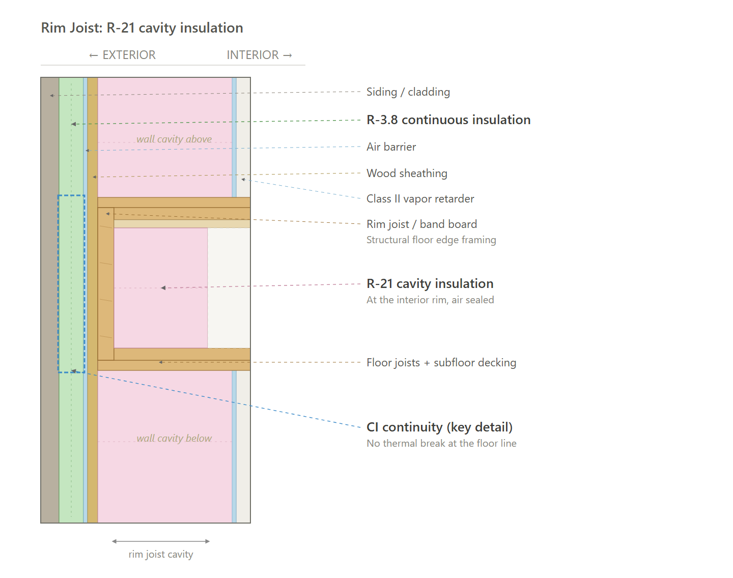
Rim Joists | ≥ R-21 rim/band insulation at floor transitions. |
Roof | Sealed attic: ≥ R-30 continuous insulation. |
Windows & Glass Doors | High performance, U ≤ 0.27 / SHGC ≤ 0.30. (Product Rec). |
Doors | Opaque door, U ≤ 0.20 (R-5.0). |
Air Sealing | ≤ 0.27 CFM50 per sqft of shell; tested. (Air Sealing Protocol) |
HVAC | Ducted air-source heat pump (as modeled); SEER2 ≥ 17.5; HSPF2 ≥ 10.5. See HVAC Design Loads. (Product Rec). |
Ductwork | Supply and return ducts in conditioned space insulated to code minimum. |
Duct Sealing | ≤ greater of 80 CFM25 or 8 CFM25 per 100 sqft of conditioned floor area; tested at final. (Duct Sealing Protocol) |
HVAC Grading | Fan Flow Test: Grade II |
Mechanical Ventilation | In-unit ERV (Product Rec). |
Local Mechanical Exhaust | Bathroom(s): at least 50 CFM intermittent and up to 3.0 sones, or at least 20 CFM continuous and up to 2.0 sones. |
Thermostats | Programmable thermostat (as modeled). |
DHW | 1-Bedroom: Heat pump water heater (HPWH) (as modeled); UEF ≥ 3.88; 40 gal (Product Rec). |
DHW Piping | Supply piping insulated to ≥ R-3. |
Water Fixtures | WaterSense certified (Lavatory ≤ 1.2 GPM; Shower ≤ 2.0 GPM; Kitchen ≤ 2.2 GPM). |
Refrigerator | ≤ 600 kWh/yr; electric. (Product Rec). |
Dishwasher | ≤ 269 kWh/yr; electric. (Product Rec). |
Clothes Washer | IMEF ≥ 2.06; IWF ≤ 4.2; ≤ 152 kWh/yr; electric. (Product Rec). |
Clothes Dryer | Heat pump dryer; ventless; CEF ≥ 6. (Product Rec). |
Stove / Oven | Electric range. (Product Rec). |
Lighting | ≥ 100% high-efficacy (LED). |
Solar Ready | N/A |
EV Ready | At least 20% of parking spaces wired EV-ready (40-amp Level II; shared circuits with load management allowed). |
HPWH Ready | N/A |
Paperwork & Modeling | ENERGY STAR energy model to the target (per-unit HERS or whole-building ASHRAE path), the ENERGY STAR design-review checklist and multifamily workbook, and an HVAC design report. |
Testing & Verification | ENERGY STAR field verification: pre-drywall and final inspections, unit air-tightness (blower door), duct-leakage, ventilation and exhaust airflow, and HVAC functional testing. |
Recommended Design - Common Areas
Item | Common Areas (Residential Building) |
|---|---|
Exterior Walls | Floors 1-2: steel studs, ≥ R-21 cavity plus ≥ R-3.8 continuous. |
Below Grade Walls | Basement foundation wall. |
Corridor Walls | N/A |
Slab | Basement slab less than 10 ft below grade. |
Floor Over Unconditioned Space | ≥ R-30 cavity. |
Floor Over Garage | N/A |
Floor Over Podium | N/A |
Rim Joists | ≥ R-21 rim/band insulation at floor transitions. |
Roof | Sealed attic: ≥ R-19 insulation + ≥ R-30 continuous insulation. |
Windows & Glass Doors | Fixed U ≤ 0.34. |
Doors | Glazed entrance U ≤ 0.60, SHGC ≤ 0.40. |
Air Sealing | Continuous air barrier for these spaces. |
HVAC | Ducted split HP: SEER2 15.2 / HSPF2 7.8. |
Ductwork | Ducts and air handlers serving these spaces are in conditioned space. |
Duct Sealing | Supply, return, and exhaust ducts and plenums serving these spaces are sealed at transverse joints, longitudinal seams, and duct wall penetrations. |
HVAC Grading | N/A |
Mechanical Ventilation | Outdoor air to the community space and the hallways, at the ASHRAE 62.1 Section 6 rate for that space. |
Local Mechanical Exhaust | N/A |
Thermostats | Programmable thermostat. |
DHW | electric tank or instant hot water heater, UEF ≥ 0.93 |
DHW Piping | R-3 (1.5 in. and smaller); R-4 (larger) |
Water Fixtures | WaterSense |
Refrigerator | N/A |
Dishwasher | N/A |
Clothes Washer | N/A |
Clothes Dryer | N/A |
Stove / Oven | N/A |
Lighting | 100% LED. |
Lighting Controls | Occupant sensors in the community space, hallways, and basement storage. |
Solar Ready | N/A |
EV Ready | 20% of parking spaces EV-ready. |
HPWH Ready | N/A |
Electric Readiness | N/A |
Vestibules | Self-closing vestibule at public building entrances; exempt if building under 3,000 sqft, or for employee-only/mechanical room doors, dwelling unit doors, revolving doors, or air curtains. |
Efficiency Credits | N/A |
Paperwork & Modeling | HERS index certificate at permit and at certificate of occupancy. |
Testing & Verification | Hallways, stairwells, and enclosed common spaces not greater than 1,500 sqft verified by inspection of the continuous air barrier. |
Assembly Moisture Check
This section shows which air and vapor barriers are needed, and why.
Inputs
Item | Value |
|---|---|
Climate zone | 5A |
Indoor air | 70 F, 35% RH |
Dewpoint of that indoor air | 41 F |
Outdoor air | 9 F |
Code | 2021 IBC Section 1404.3, Table 1404.3(2) |
Exterior Walls, floors 1-2 (steel studs), PROPOSED
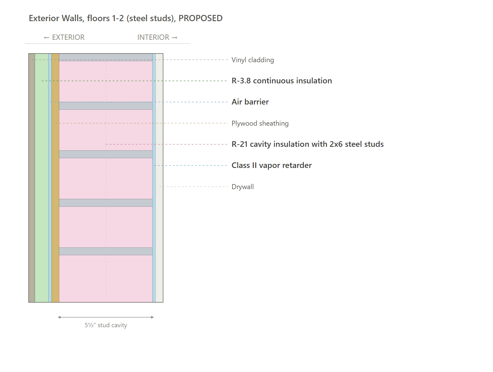
Conclusion: This wall is 2x6 steel studs on floors 1-2. The dewpoint table is a wood-frame bay, so this wall has no bay table. The layers are gypsum, R-21 cavity insulation, plywood sheathing, R-3.8 continuous insulation, and vinyl cladding. R-3.8 continuous insulation is below the Class III minimum in 2021 IBC Table 1404.3(2) for a 2x6 wall in climate zone 5 (R-7.5), so the vapor retarder is Class II on the gypsum. The cavity insulation is air-permeable, so the air barrier is on the sheathing. Same at the rim. Keep the R-3.8 going over the band. The wood floors use that same continuous layer, so there is no insulation transition.
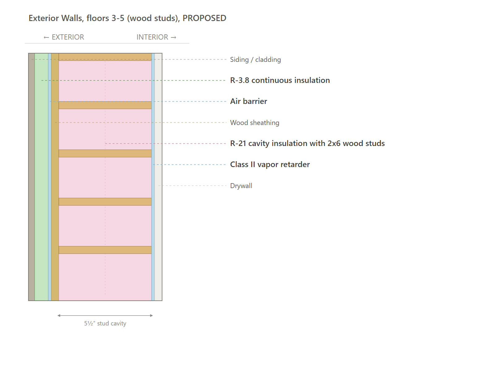
Exterior Walls, floors 3-5 (wood studs), PROPOSED
# | Layer (inside to outside) | R | Running R | Temp | Dewpoint target | Vs dewpoint |
|---|---|---|---|---|---|---|
1 | Drywall | 1.13 | 1.13 | 67.4 F | 41 F | OK |
2 | Class II vapor retarder | 0.00 | 1.13 | 67.4 F | 41 F | OK |
3 | R-21 cavity insulation with 2x6 wood studs | 21.00 | 22.13 | 19.5 F | 41 F | First below dewpoint |
4 | Wood sheathing | 0.62 | 22.75 | 18.1 F | 41 F | Below dewpoint |
5 | Air barrier | 0.00 | 22.75 | 18.1 F | 41 F | Below dewpoint |
6 | R-3.8 continuous insulation | 3.80 | 26.55 | 9.4 F | 41 F | Below dewpoint |
7 | Siding / cladding | 0.17 | 26.72 | 9.0 F | 41 F | Below dewpoint |
Conclusion: Layer 3 is the first row below dewpoint. It is the cold plane we protect. Indoor moisture can turn to water if it gets there, and can eventually cause mold. It can get there two ways. It gets there through the drywall, which is why the vapor retarder is on the inside of the wall. It also gets there through holes (outlets, gaps, plates), which is why the air barrier is on the sheathing. Same at the rim. Keep the R-3.8 going over the band. The steel floors use this same R-3.8 continuous layer, so there is no insulation transition.
Exterior Walls, floors 1-2 (steel studs), HPWH
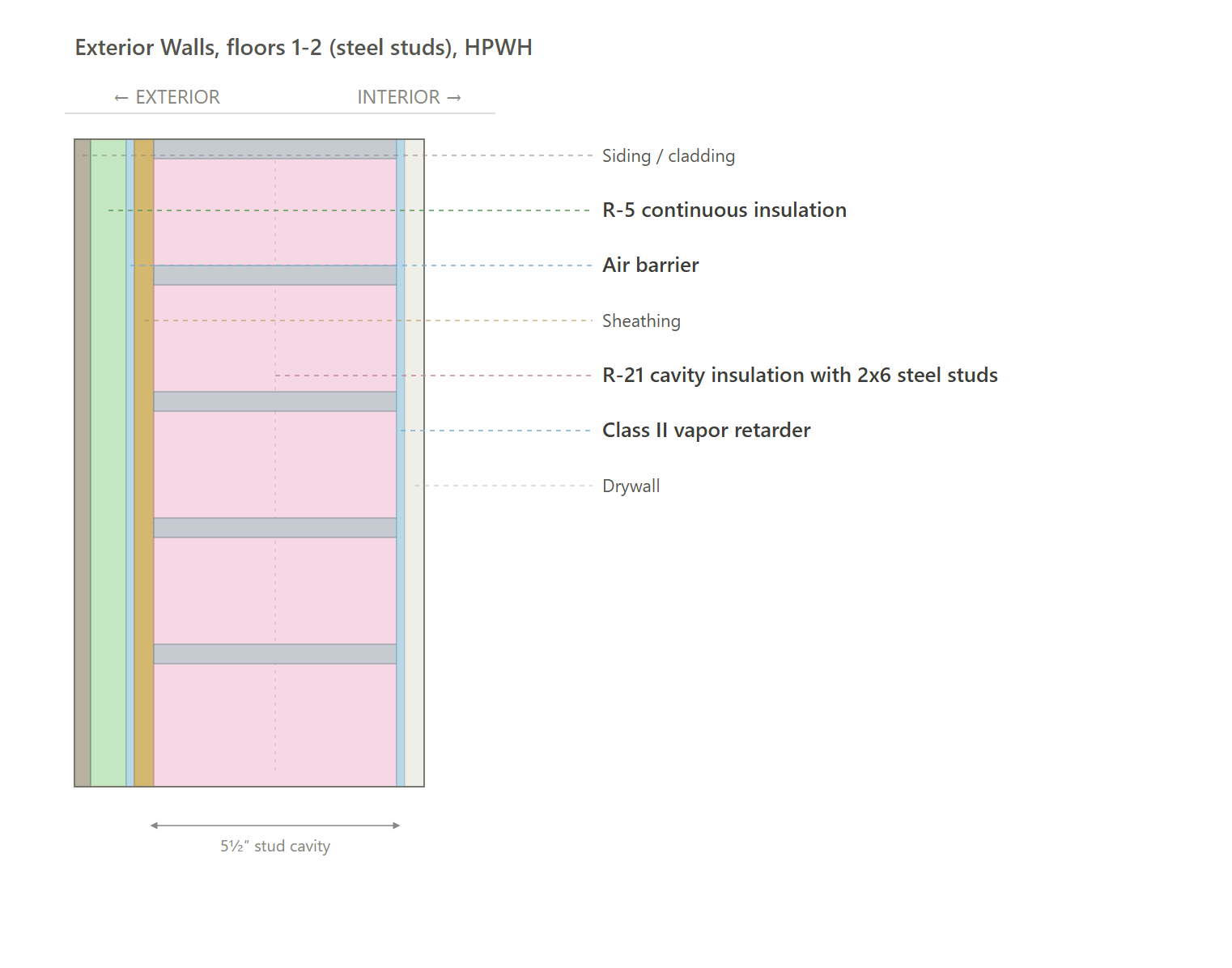
Conclusion: This wall is 2x6 steel studs on floors 1-2. The dewpoint table is a wood-frame bay, so this wall has no bay table. The layers are gypsum, R-21 cavity insulation, sheathing, R-5 continuous insulation, and cladding. R-5 continuous insulation is below the Class III minimum in 2021 IBC Table 1404.3(2) for a 2x6 wall in climate zone 5 (R-7.5), so the vapor retarder is Class II on the gypsum. The cavity insulation is air-permeable, so the air barrier is on the sheathing. Keep the R-5 going over the band.
Exterior Walls, floors 3-5 (wood studs), HPWH
# | Layer (inside to outside) | R | Running R | Temp | Dewpoint target | Vs dewpoint |
|---|---|---|---|---|---|---|
1 | Drywall | 1.13 | 1.13 | 67.2 F | 41 F | OK |
2 | Class II vapor retarder | 0.00 | 1.13 | 67.2 F | 41 F | OK |
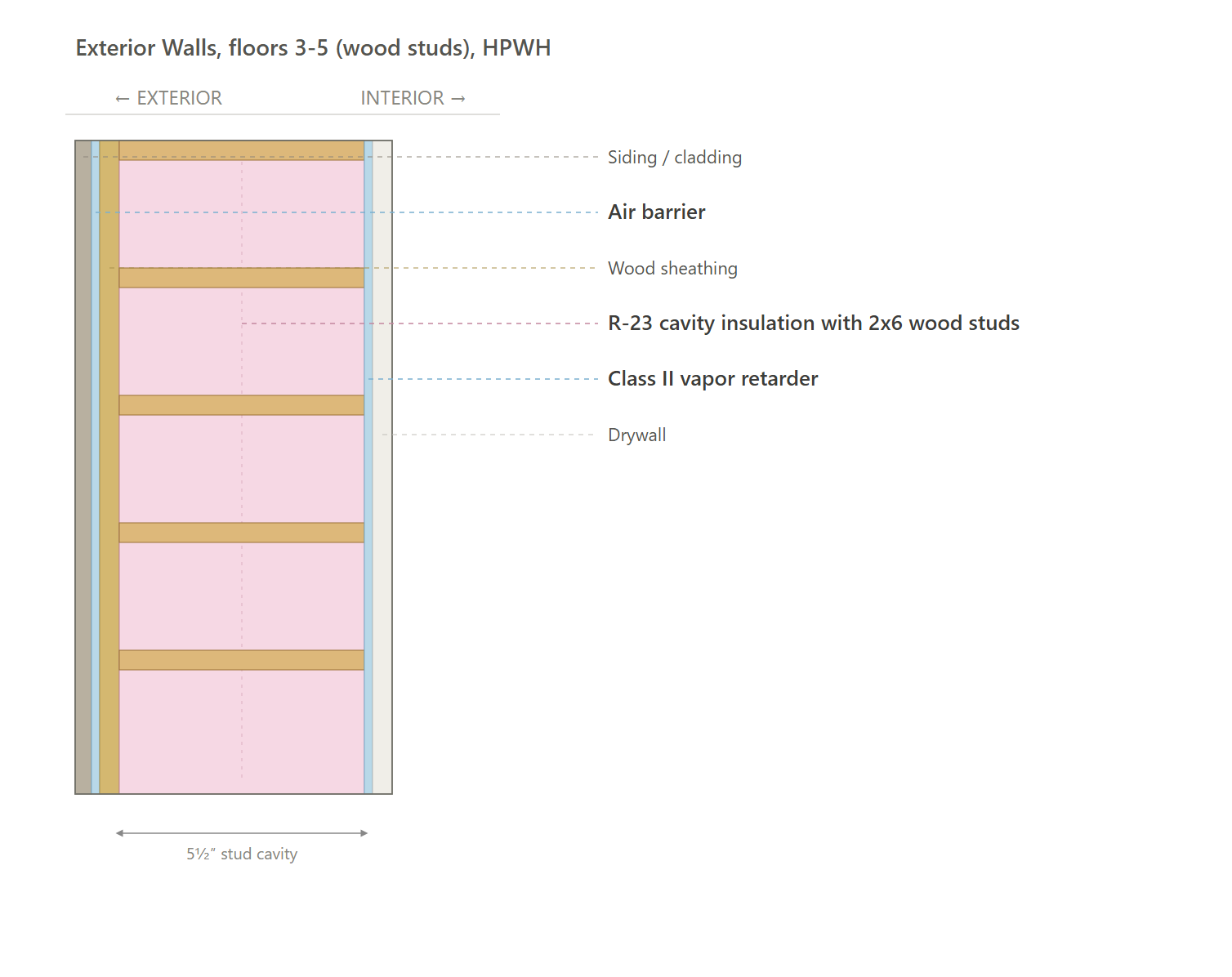
3 | R-23 cavity insulation with 2x6 wood studs | 23.00 | 24.13 | 10.9 F | 41 F | First below dewpoint |
4 | Wood sheathing | 0.62 | 24.75 | 9.4 F | 41 F | Below dewpoint |
5 | Air barrier | 0.00 | 24.75 | 9.4 F | 41 F | Below dewpoint |
6 | Siding / cladding | 0.17 | 24.92 | 9.0 F | 41 F | Below dewpoint |
Conclusion: Layer 3 is the first row below dewpoint. It is the cold plane we protect. Indoor moisture can turn to water if it gets there, and can eventually cause mold. It can get there two ways. It gets there through the drywall, which is why the vapor retarder is on the inside of the wall. It also gets there through holes (outlets, gaps, plates), which is why the air barrier is on the sheathing. Same at the rim.
Exterior Walls, steel stud alternative (both paths)
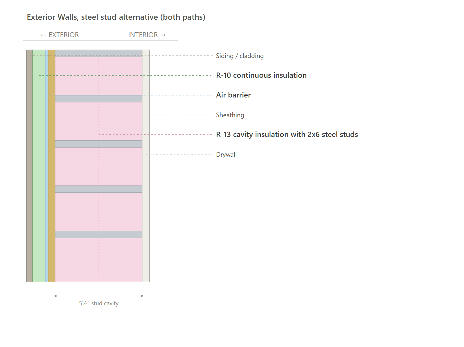
Conclusion: This is the alternative for the steel wall on both paths. It is not the specified wall. The studs are 2x6 steel. The dewpoint table is a wood-frame bay, so this wall has no bay table. The layers are gypsum, R-13 cavity insulation, sheathing, R-10 continuous insulation, and cladding. R-10 continuous insulation meets the Class III minimum in 2021 IBC Table 1404.3(2) for a 2x6 wall in climate zone 5 (R-7.5), so the vapor retarder is Class III on the gypsum. The cavity insulation is air-permeable, so the air barrier is on the sheathing. If this alternative is built, keep the R-10 going over the band.
Floor Over Unconditioned Space, R-30 cavity
# | Layer (inside to outside) | R | Running R | Temp | Dewpoint target | Vs dewpoint |
|---|---|---|---|---|---|---|
1 | Floor finish | 1.13 | 1.13 | 67.8 F | 41 F | OK |
2 | R-30 cavity insulation | 30.00 | 31.13 | 9.3 F | 41 F | First below dewpoint |
3 | Air barrier | 0.00 | 31.13 | 9.3 F | 41 F | Below dewpoint |
4 | Unconditioned | 0.17 | 31.30 | 9.0 F | 41 F | Below dewpoint |
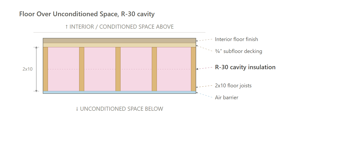
Conclusion: Layer 2 is the first row below dewpoint. It is the cold plane we protect. Indoor moisture can turn to water if it gets there, and can eventually cause mold. The spray foam is the vapor retarder. It can still get there through holes, which is why the air barrier is at the floor so unconditioned air cannot enter the unit.
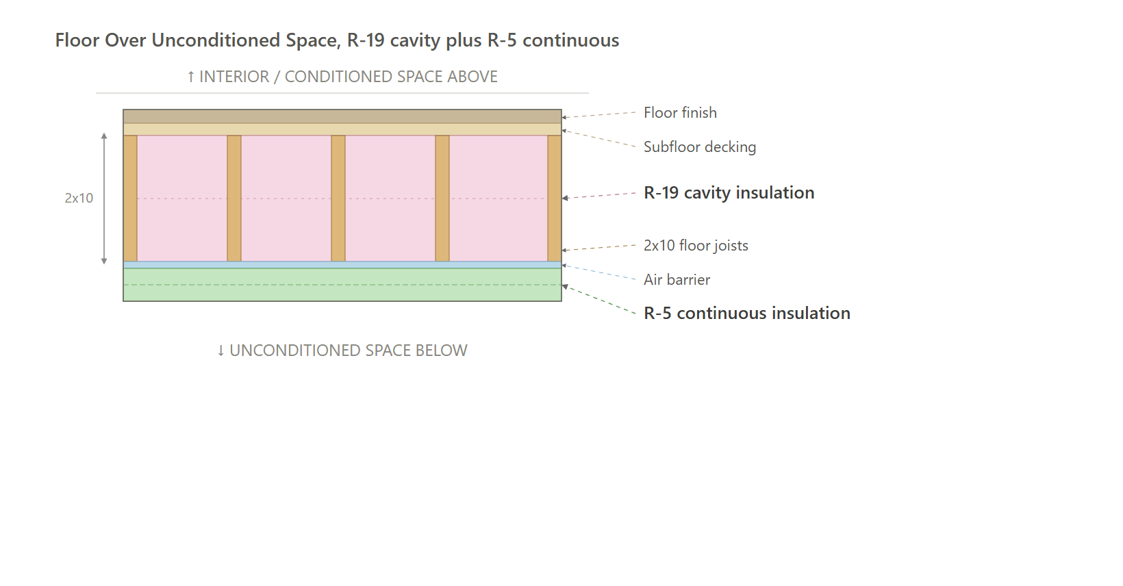
Floor Over Unconditioned Space, R-19 cavity plus R-5 continuous
# | Layer (inside to outside) | R | Running R | Temp | Dewpoint target | Vs dewpoint |
|---|---|---|---|---|---|---|
1 | Floor finish | 1.13 | 1.13 | 67.3 F | 41 F | OK |
2 | R-19 cavity insulation | 19.00 | 20.13 | 21.5 F | 41 F | First below dewpoint |
3 | Air barrier | 0.00 | 20.13 | 21.5 F | 41 F | Below dewpoint |
4 | R-5 continuous insulation | 5.00 | 25.13 | 9.4 F | 41 F | Below dewpoint |
5 | Unconditioned | 0.17 | 25.30 | 9.0 F | 41 F | Below dewpoint |
Conclusion: Layer 2 is the first row below dewpoint. It is the cold plane we protect. Indoor moisture can turn to water if it gets there, and can eventually cause mold. It can get there through holes, which is why the air barrier is at the insulated plane, not a drop-in ceiling.
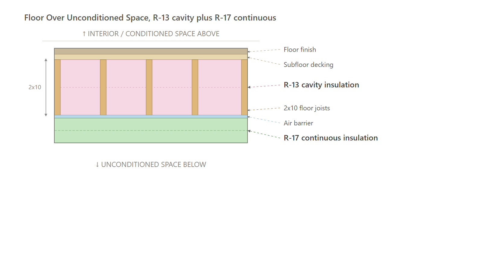
Floor Over Unconditioned Space, R-13 cavity plus R-17 continuous
# | Layer (inside to outside) | R | Running R | Temp | Dewpoint target | Vs dewpoint |
|---|---|---|---|---|---|---|
1 | Floor finish | 1.13 | 1.13 | 67.8 F | 41 F | OK |
2 | R-13 cavity insulation | 13.00 | 14.13 | 42.5 F | 41 F | OK |
3 | Air barrier | 0.00 | 14.13 | 42.5 F | 41 F | OK |
4 | R-17 continuous insulation | 17.00 | 31.13 | 9.3 F | 41 F | First below dewpoint |
5 | Unconditioned | 0.17 | 31.30 | 9.0 F | 41 F | Below dewpoint |
Conclusion: Layer 4 is the first row below dewpoint. It is the cold plane we protect. Indoor moisture can turn to water if it gets there, and can eventually cause mold. It can get there through holes, which is why the air barrier is at the insulated plane, not a drop-in ceiling.
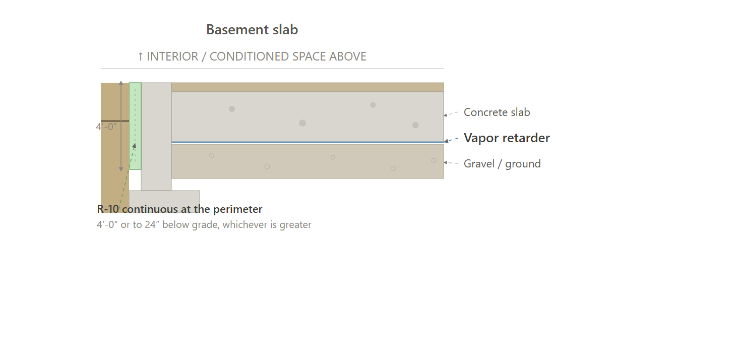
Slab
# | Layer (inside to outside) | R | Running R | Temp | Dewpoint target | Vs dewpoint |
|---|---|---|---|---|---|---|
1 | Concrete slab | 0.50 | 0.50 | 69.0 F | 41 F | OK |
2 | Vapor retarder | 0.00 | 0.50 | 69.0 F | 41 F | OK |
3 | R-10 continuous at the perimeter | 10.00 | 10.50 | 50.0 F | 41 F | OK |
4 | Gravel / ground | 0.00 | 10.50 | 50.0 F | 41 F | OK |
Conclusion: No row drops below dewpoint. This is not the wall problem. Indoor air is not leaking to a cold sheathing. The vapor retarder is under the slab to stop moisture coming up from the ground. The slab itself is the air barrier. This is the basement slab less than 10 ft below grade. Insulation is R-10 continuous at the perimeter.
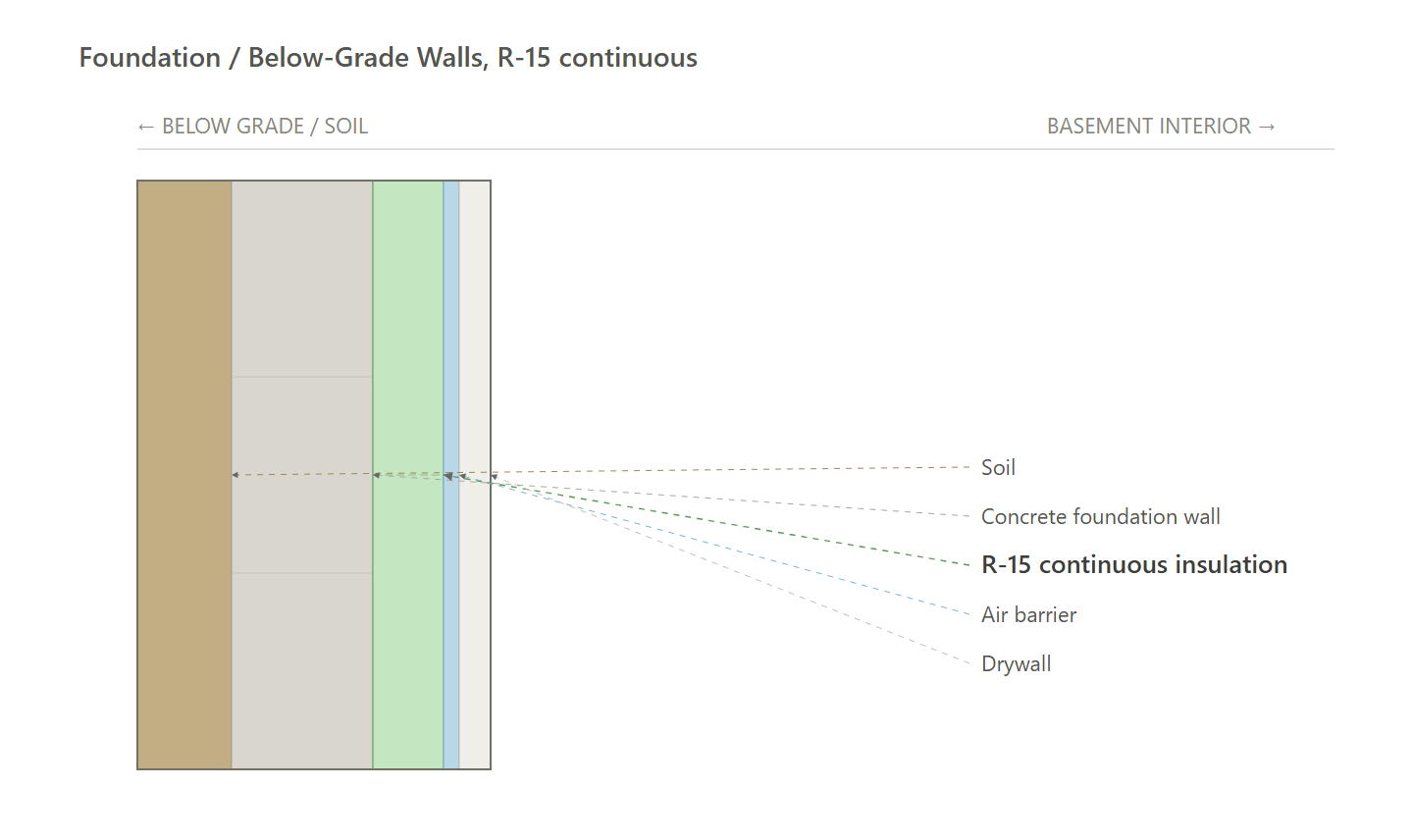
Foundation / Below-Grade Walls, R-15 continuous
# | Layer (inside to outside) | R | Running R | Temp | Dewpoint target | Vs dewpoint |
|---|---|---|---|---|---|---|
1 | Drywall | 1.13 | 1.13 | 65.9 F | 41 F | OK |
2 | Air barrier | 0.00 | 1.13 | 65.9 F | 41 F | OK |
3 | R-15 continuous insulation | 15.00 | 16.13 | 11.4 F | 41 F | First below dewpoint |
4 | Concrete foundation wall | 0.50 | 16.63 | 9.6 F | 41 F | Below dewpoint |
5 | Soil | 0.17 | 16.80 | 9.0 F | 41 F | Below dewpoint |
Conclusion: Layer 3 is the first row below dewpoint. It is the cold plane we protect. Indoor moisture can turn to water if it gets there, and can eventually cause mold. The continuous insulation is the vapor retarder. It can still get there through holes, which is why the air barrier is on the interior face of the insulation so room air cannot reach the cold concrete. This is the basement foundation wall, from the top of the wall to 10 ft below grade or the basement floor, whichever is less.
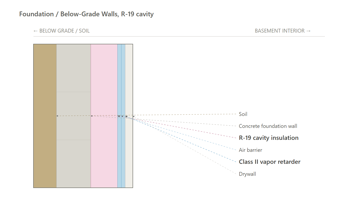
Foundation / Below-Grade Walls, R-19 cavity
# | Layer (inside to outside) | R | Running R | Temp | Dewpoint target | Vs dewpoint |
|---|---|---|---|---|---|---|
1 | Drywall | 1.13 | 1.13 | 66.7 F | 41 F | OK |
2 | Class II vapor retarder | 0.00 | 1.13 | 66.7 F | 41 F | OK |
3 | Air barrier | 0.00 | 1.13 | 66.7 F | 41 F | OK |
4 | R-19 cavity insulation | 19.00 | 20.13 | 11.0 F | 41 F | First below dewpoint |
5 | Concrete foundation wall | 0.50 | 20.63 | 9.5 F | 41 F | Below dewpoint |
6 | Soil | 0.17 | 20.80 | 9.0 F | 41 F | Below dewpoint |
Conclusion: Layer 4 is the first row below dewpoint. It is the cold plane we protect. Indoor moisture can turn to water if it gets there, and can eventually cause mold. It can get there through the drywall, which is why the vapor retarder is Class II on the inside of the wall. It can also get there through holes, which is why the air barrier is on the interior face of the insulation so room air cannot reach the cold concrete. This is the basement foundation wall, from the top of the wall to 10 ft below grade or the basement floor, whichever is less.
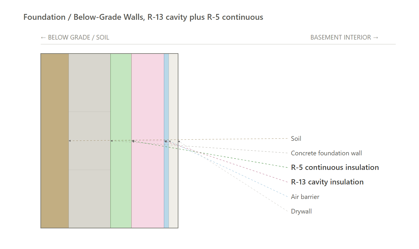
Foundation / Below-Grade Walls, R-13 cavity plus R-5 continuous
# | Layer (inside to outside) | R | Running R | Temp | Dewpoint target | Vs dewpoint |
|---|---|---|---|---|---|---|
1 | Drywall | 1.13 | 1.13 | 66.5 F | 41 F | OK |
2 | Air barrier | 0.00 | 1.13 | 66.5 F | 41 F | OK |
3 | R-13 cavity insulation | 13.00 | 14.13 | 26.5 F | 41 F | First below dewpoint |
4 | R-5 continuous insulation | 5.00 | 19.13 | 11.1 F | 41 F | Below dewpoint |
5 | Concrete foundation wall | 0.50 | 19.63 | 9.5 F | 41 F | Below dewpoint |
6 | Soil | 0.17 | 19.80 | 9.0 F | 41 F | Below dewpoint |
Conclusion: Layer 3 is the first row below dewpoint. It is the cold plane we protect. Indoor moisture can turn to water if it gets there, and can eventually cause mold. The continuous insulation is the vapor retarder. It can still get there through holes, which is why the air barrier is on the interior face of the insulation so room air cannot reach the cold concrete. This is the basement foundation wall, from the top of the wall to 10 ft below grade or the basement floor, whichever is less.
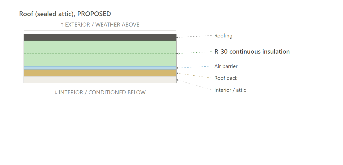
Roof (sealed attic), PROPOSED
# | Layer (inside to outside) | R | Running R | Temp | Dewpoint target | Vs dewpoint |
|---|---|---|---|---|---|---|
1 | Interior / attic | 0.68 | 0.68 | 68.7 F | 41 F | OK |
2 | Roof deck | 0.62 | 1.30 | 67.5 F | 41 F | OK |
3 | Air barrier | 0.00 | 1.30 | 67.5 F | 41 F | OK |
4 | R-30 continuous insulation | 30.00 | 31.30 | 9.3 F | 41 F | First below dewpoint |
5 | Roofing | 0.17 | 31.47 | 9.0 F | 41 F | Below dewpoint |
Conclusion: Layer 4 is the first row below dewpoint. That plane is outside the deck, in the continuous insulation. The deck stays warm. Indoor moisture can turn to water if it gets to a cold face, and can eventually cause mold. The air barrier is on the deck so room air cannot leak into the insulation.
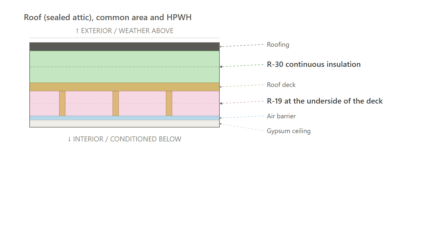
Roof (sealed attic), common area and HPWH
# | Layer (inside to outside) | R | Running R | Temp | Dewpoint target | Vs dewpoint |
|---|---|---|---|---|---|---|
1 | Gypsum ceiling | 1.13 | 1.13 | 68.6 F | 41 F | OK |
2 | Air barrier | 0.00 | 1.13 | 68.6 F | 41 F | OK |
3 | R-19 at the underside of the deck | 19.00 | 20.13 | 45.9 F | 41 F | OK |
4 | Roof deck | 0.62 | 20.75 | 45.1 F | 41 F | OK |
5 | R-30 continuous insulation | 30.00 | 50.75 | 9.2 F | 41 F | First below dewpoint |
6 | Roofing | 0.17 | 50.92 | 9.0 F | 41 F | Below dewpoint |
Conclusion: Layer 5 is the first row below dewpoint. It is the cold plane we protect. Indoor moisture can turn to water if it gets there, and can eventually cause mold. It can get there through the insulation strapped under the deck, which is why the air barrier is the sealed gypsum on the room side of that insulation. The layer on the deck does not satisfy this.
Exterior Walls, floors 1-2, 2x6 steel, R-21 cavity plus R-3.8 continuous (Recommended Design)
Exterior Walls, floors 3-5, 2x6 wood, R-21 cavity plus R-3.8 continuous (Recommended Design)
Exterior Walls, floors 1-2, 2x6 steel, R-21 cavity plus R-5 continuous (HPWH)
Exterior Walls, floors 3-5, 2x6 wood, R-23 cavity, no continuous insulation (HPWH)
Exterior Walls, steel stud alternative, R-13 cavity plus R-10 continuous (both paths)
Floor Over Unconditioned Space, R-30 cavity (common area)
Floor Over Unconditioned Space, R-19 cavity plus R-5 continuous (common area)
Floor Over Unconditioned Space, R-13 cavity plus R-17 continuous (common area)
Basement slab, R-10 continuous at the perimeter (common area)
Foundation / Below-Grade Walls, R-15 continuous (common area)
Foundation / Below-Grade Walls, R-19 cavity (common area)
Foundation / Below-Grade Walls, R-13 cavity plus R-5 continuous (common area)
Roof, sealed attic, R-30 continuous (Recommended Design)
Roof, sealed attic, R-19 underside plus R-30 continuous (common area and HPWH)
Rim Joists, R-21 cavity, R-3.8 continuous over the band (Recommended Design)
Path Comparison
This section shows the detailed requirements and incentives for each path we compared, basically showing our work of how we determined the recommended path is the most affordable way of meeting energy code compliance.
Path Comparison - Incentives
PROPOSED / HPWH: $71,750 - $133,250
- MassSave Multifamily Program Energy Star Tier ($71,750) (Program Breakdown): You get this rebate for having your building(s) certified for the Energy Star MFNC v1.2 program. This requires pre-approval via an application to be submitted before construction starts. This rebate comes in the form of a check within 4 months of certification documentation being provided to MassSave, typically this is 4 months after construction is complete.
- DOER Alternative Energy Credits ($0 - $61,500) (Program Breakdown): This rebate is received for installing APS eligible air source heat pumps (click here for the list). There is an extensive process to get this incentive. It comes in the form of a check approximately 6-12 months after the heat pumps are installed and fully operational.
- IMPORTANT: Although an estimate is provided, this incentive can vary widely typically between $300-1,500 per heat pump. It's based on expected kWh usage of the system as well as the market value of the alternative energy credits when sold.
- Risks: Massachusetts is rewriting this program right now. The House bill would stop the state from accepting new applications on January 1, 2028, the Senate version leaves heat pumps out of that cutoff, and the two are in conference. The application needs the equipment installed and operating, so a project that will not reach that point before the deadline should treat this as upside rather than a budgeted line.
Path Comparison - Net Cost Summary
Path | Total Cost $/sf | Total Incentives $/sf | Net $/sf | OpEx Factor |
|---|---|---|---|---|
PROPOSED | $59.32 | $1.90 | $58.46 | 1.02 |
HPWH | $61.37 | $1.90 | $60.64 | 1.02 |
Path Comparison - Envelope
Item | Path | Detailed Specifications | Cost $/sf | Incentive $/sf | Net $/sf | OpEx |
|---|---|---|---|---|---|---|
Exterior Walls | HPWH | Floors 1-2: ≥ R-21 cavity insulation (2x6 steel @ 16" o.c.) with ≥ R-5 continuous exterior insulation. Floors 3-5: ≥ R-23 cavity insulation (2x6 wood @ 16" o.c.), no continuous insulation. Suitable alternative for the steel wall: ≥ R-13 cavity plus ≥ R-10 continuous. | $5.91 | $0.00 | $5.91 | 0.95 |
PROPOSED | Floors 1-2: ≥ R-21 cavity insulation (2x6 steel @ 16" o.c., 5.5 in) with ≥ R-3.8 polyiso continuous exterior insulation (1 in). Floors 3-5: ≥ R-21 cavity insulation (2x6 wood @ 16" o.c., 5.5 in) with ≥ R-3.8 polyiso continuous exterior insulation (1 in). Steel and wood share the same R-3.8 continuous insulation, so there is no insulation transition between floors. Suitable alternative for the steel wall: ≥ R-13 cavity plus ≥ R-10 continuous. | $6.56 | $0.00 | $6.56 | 0.90 | |
Below Grade Walls | HPWH | N/A | $0.00 | $0.00 | $0.00 | 1.00 |
PROPOSED | N/A | $0.00 | $0.00 | $0.00 | 1.00 | |
Corridor Walls | HPWH | N/A | $0.00 | $0.00 | $0.00 | 1.00 |
PROPOSED | N/A | $0.00 | $0.00 | $0.00 | 1.00 | |
Slab | HPWH | N/A | $0.00 | $0.00 | $0.00 | 1.00 |
PROPOSED | N/A | $0.00 | $0.00 | $0.00 | 1.00 | |
Floor Over Unconditioned Space | HPWH | N/A | $0.00 | $0.00 | $0.00 | 1.00 |
PROPOSED | N/A | $0.00 | $0.00 | $0.00 | 1.00 | |
Floor Over Garage | HPWH | N/A | $0.00 | $0.00 | $0.00 | 1.00 |
PROPOSED | N/A | $0.00 | $0.00 | $0.00 | 1.00 | |
Floor Over Podium | HPWH | N/A | $0.00 | $0.00 | $0.00 | 1.00 |
PROPOSED | N/A | $0.00 | $0.00 | $0.00 | 1.00 | |
Rim Joists | HPWH | ≥ R-21 rim/band insulation at floor transitions. | $0.20 | $0.00 | $0.20 | 0.95 |
PROPOSED | ≥ R-21 rim/band insulation at floor transitions. | $0.20 | $0.00 | $0.20 | 0.95 | |
Roof | HPWH | Sealed attic: ≥ R-19 insulation + ≥ R-30 continuous insulation. | $2.79 | $0.00 | $2.79 | 1.10 |
PROPOSED | Sealed attic: ≥ R-30 continuous insulation. | $1.40 | $0.00 | $1.40 | 1.10 | |
Windows & Glass Doors | HPWH | High performance, U ≤ 0.25 / SHGC ≤ 0.25. | $9.49 | $0.00 | $9.49 | 1.00 |
PROPOSED | High performance, U ≤ 0.27 / SHGC ≤ 0.30. | $8.18 | $0.00 | $8.18 | 1.00 | |
Doors | HPWH | Opaque door, U ≤ 0.20 (R-5.0). | $0.35 | $0.00 | $0.35 | 0.95 |
PROPOSED | Opaque door, U ≤ 0.20 (R-5.0). | $0.35 | $0.00 | $0.35 | 0.95 | |
Air Sealing | HPWH | ≤ 0.27 CFM50 per sqft of shell; tested. | $1.29 | $0.00 | $1.29 | 0.95 |
PROPOSED | ≤ 0.27 CFM50 per sqft of shell; tested. | $1.29 | $0.00 | $1.29 | 0.95 |
Path Comparison - Mechanical
Item | Path | Detailed Specifications | Cost $/sf | Incentive $/sf | Net $/sf | OpEx |
|---|---|---|---|---|---|---|
HVAC | HPWH | Ducted air-source heat pump (as modeled); SEER2 ≥ 17.5; HSPF2 ≥ 10.5. See HVAC Design Loads. | $15.82 | $0.00 | $15.82 | 1.15 |
PROPOSED | Ducted air-source heat pump (as modeled); SEER2 ≥ 17.5; HSPF2 ≥ 10.5. See HVAC Design Loads. | $15.82 | $0.00 | $15.82 | 1.15 | |
Ductwork | HPWH | Supply and return ducts in conditioned space insulated to code minimum. | $5.18 | $0.00 | $5.18 | 1.00 |
PROPOSED | Supply and return ducts in conditioned space insulated to code minimum. | $5.18 | $0.00 | $5.18 | 1.00 | |
Duct Sealing | HPWH | ≤ greater of 80 CFM25 or 8 CFM25 per 100 sqft of conditioned floor area; tested at final. | $0.89 | $0.00 | $0.89 | 1.00 |
PROPOSED | ≤ greater of 80 CFM25 or 8 CFM25 per 100 sqft of conditioned floor area; tested at final. | $0.89 | $0.00 | $0.89 | 1.00 | |
HVAC Grading | HPWH | Fan Flow Test: Grade II | $0.00 | $0.00 | $0.00 | 1.00 |
PROPOSED | Fan Flow Test: Grade II | $0.00 | $0.00 | $0.00 | 1.00 | |
Mechanical Ventilation | HPWH | In-unit ERV | $2.28 | $0.00 | $2.28 | 1.20 |
PROPOSED | In-unit ERV | $2.28 | $0.00 | $2.28 | 1.20 | |
Local Mechanical Exhaust | HPWH | Bathroom(s): at least 50 CFM intermittent and up to 3.0 sones, or at least 20 CFM continuous and up to 2.0 sones. | $1.26 | $0.00 | $1.26 | 1.05 |
PROPOSED | Bathroom(s): at least 50 CFM intermittent and up to 3.0 sones, or at least 20 CFM continuous and up to 2.0 sones. | $1.26 | $0.00 | $1.26 | 1.05 | |
Thermostats | HPWH | Programmable thermostat (as modeled). | $0.15 | $0.00 | $0.15 | 1.05 |
PROPOSED | Programmable thermostat (as modeled). | $0.15 | $0.00 | $0.15 | 1.05 |
Path Comparison - Plumbing & Appliances
Item | Path | Detailed Specifications | Cost $/sf | Incentive $/sf | Net $/sf | OpEx |
|---|---|---|---|---|---|---|
DHW | HPWH | 1-Bedroom: Heat pump water heater (HPWH) (as modeled); UEF ≥ 3.88; 40 gal | $3.40 | $0.00 | $3.40 | 1.20 |
PROPOSED | 1-Bedroom: Heat pump water heater (HPWH) (as modeled); UEF ≥ 3.88; 40 gal | $3.40 | $0.00 | $3.40 | 1.20 | |
DHW Piping | HPWH | Supply piping insulated to ≥ R-3. | $0.89 | $0.00 | $0.89 | 0.95 |
PROPOSED | Supply piping insulated to ≥ R-3. | $0.89 | $0.00 | $0.89 | 0.95 | |
Water Fixtures | HPWH | WaterSense certified (Lavatory ≤ 1.2 GPM; Shower ≤ 2.0 GPM; Kitchen ≤ 2.2 GPM). | $2.22 | $0.00 | $2.22 | 1.00 |
PROPOSED | WaterSense certified (Lavatory ≤ 1.2 GPM; Shower ≤ 2.0 GPM; Kitchen ≤ 2.2 GPM). | $2.22 | $0.00 | $2.22 | 1.00 | |
Refrigerator | HPWH | ≤ 600 kWh/yr; electric. | $0.90 | $0.00 | $0.90 | 1.10 |
PROPOSED | ≤ 600 kWh/yr; electric. | $0.90 | $0.00 | $0.90 | 1.10 | |
Dishwasher | HPWH | ≤ 269 kWh/yr; electric. | $0.52 | $0.00 | $0.52 | 1.10 |
PROPOSED | ≤ 269 kWh/yr; electric. | $0.52 | $0.00 | $0.52 | 1.10 | |
Clothes Washer | HPWH | IMEF ≥ 2.06; IWF ≤ 4.2; ≤ 152 kWh/yr; electric. | $0.63 | $0.00 | $0.63 | 1.10 |
PROPOSED | IMEF ≥ 2.06; IWF ≤ 4.2; ≤ 152 kWh/yr; electric. | $0.63 | $0.00 | $0.63 | 1.10 | |
Clothes Dryer | HPWH | Heat pump dryer; ventless; CEF ≥ 6. | $1.22 | $0.00 | $1.22 | 1.00 |
PROPOSED | Heat pump dryer; ventless; CEF ≥ 6. | $1.22 | $0.00 | $1.22 | 1.00 | |
Stove / Oven | HPWH | Electric range. | $0.71 | $0.00 | $0.71 | 1.00 |
PROPOSED | Electric range. | $0.71 | $0.00 | $0.71 | 1.00 |
Path Comparison - Electrical
Item | Path | Detailed Specifications | Cost $/sf | Incentive $/sf | Net $/sf | OpEx |
|---|---|---|---|---|---|---|
Lighting | HPWH | ≥ 100% high-efficacy (LED). | $4.00 | $0.00 | $4.00 | 0.85 |
PROPOSED | ≥ 100% high-efficacy (LED). | $4.00 | $0.00 | $4.00 | 0.85 | |
Solar Ready | HPWH | N/A | $0.00 | $0.00 | $0.00 | 1.00 |
PROPOSED | N/A | $0.00 | $0.00 | $0.00 | 1.00 | |
EV Ready | HPWH | At least 20% of parking spaces wired EV-ready (40-amp Level II; shared circuits with load management allowed). | $0.46 | $0.00 | $0.46 | 1.00 |
PROPOSED | At least 20% of parking spaces wired EV-ready (40-amp Level II; shared circuits with load management allowed). | $0.46 | $0.00 | $0.46 | 1.00 | |
HPWH Ready | HPWH | N/A | $0.00 | $0.00 | $0.00 | 1.00 |
PROPOSED | N/A | $0.00 | $0.00 | $0.00 | 1.00 |
Path Comparison - Soft Costs & Whole-Building Incentives
Item | Path | Detailed Specifications | Cost $/sf | Incentive $/sf | Net $/sf | OpEx |
|---|---|---|---|---|---|---|
Paperwork & Modeling | HPWH | ENERGY STAR energy model to the target (per-unit HERS or whole-building ASHRAE path), the ENERGY STAR design-review checklist and multifamily workbook, and an HVAC design report. | $0.24 | $1.90 | -$1.66 | 1.00 |
PROPOSED | ENERGY STAR energy model to the target (per-unit HERS or whole-building ASHRAE path), the ENERGY STAR design-review checklist and multifamily workbook, and an HVAC design report. | $0.24 | $1.90 | -$1.66 | 1.00 | |
Testing & Verification | HPWH | ENERGY STAR field verification: pre-drywall and final inspections, unit air-tightness (blower door), duct-leakage, ventilation and exhaust airflow, and HVAC functional testing. | $0.57 | $0.00 | $0.57 | 1.00 |
PROPOSED | ENERGY STAR field verification: pre-drywall and final inspections, unit air-tightness (blower door), duct-leakage, ventilation and exhaust airflow, and HVAC functional testing. | $0.57 | $0.00 | $0.57 | 1.00 |
Additional Design Considerations Not Represented In This Study
- Smaller Heat Pumps on the Two- and Three-Bedroom Units: A smaller heat pump sized to the cooling load was not used on the two-bedroom or three-bedroom units, because heating at 5 F set the size. On both the HPWH and PROPOSED paths those units stay single-stage ducted heat pumps at 24 kBtuh. ENERGY STAR MFNC holds a single-stage unit to 130 percent of the cooling load. Cooling is over that limit on both paths: the HPWH two-bedroom is 176.5 percent of its 13.6 kBtuh cooling load and the HPWH three-bedroom is 165.5 percent of its 14.5 kBtuh load, and the PROPOSED two-bedroom is 169.0 percent of its 14.2 kBtuh load and the PROPOSED three-bedroom is 158.9 percent of its 15.1 kBtuh load. Heating at 5 F still passes, so the smaller cooling size was not used. The one-bedroom units are 12 kBtuh and pass cooling on both paths.
